
Eight MOSFET driven Power Outputs
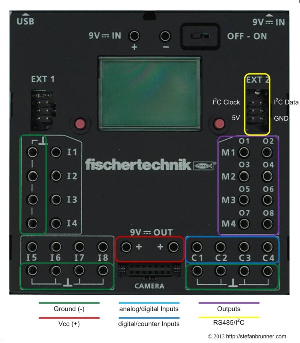
The fischertechnik ROBO TX Controller has eight outputs. All eight outputs are controlled by power MOSFETs. fischertechnik states that each port can deliver 250mA, but in fact, each port can deliver 1A to a total of 2A in output, or 250mA per port, each. This means that you can either connect two loads of 1A each or eight loads of 250mA or any combination of the two so that the sum of all loads never exceeds 2A. If you overload a port with more than 1A, the internal MOSFET driver will turn it off. The port will also be turned off if nothing is connected. The voltage is your input voltage, eg 8.4V for the battery pack minus some small voltage drop which is 0.4V or 0.8V depending on port configuration. You can pair two ports in H-bridge configuration to change polarity meant to control the spin direction of a motor - but more to that later.
Various inductive, incandescent, or LED loads can be connected. This includes motors, electro magnets, relays, pneumatic valves, and light bulbs, or loads with microcontrollers such as the fischertechnik sound brick. You cannot connect anything which interferes with the PWM or load sensor, hence anything with an RC or RL filter such as devices used in ham radio or any device which radiates high frequency back into the port such as the classic fischertechnik Mot which has an insufficient EMI filter. If you want to connect those, you need to isolate them for instance by a mechanical relay. If you wish to connect TTL or CMOS logic, you need to be watchful of the higher voltage. Most chips might be damaged if supplied with more than Vcc which is usually 5V or on some power saving chips 3.3V. A simple voltage divider out of two transistors such as two 10kΩ resistors should do the trick. Power draw by those devices is very low.
PWM Control
All ports are PWM (pulse width modulation) controlled. PWM control serves the same need as changing the voltage level for the purpose of changing the speed of a motor or the brightness of a lamp. The difference is that former days variable power supplies often burned the excess energy via a variable resistor. A PWM controller on the other hand is not changing the voltage level but switches power very fast on and off. The energy being sent to a load is measured in Duty Cycle which is the ratio between the time the power source is switched on and switched off. At a Duty Cycle of 100%, the power is switched on all the time. In contrast, a Duty Cycle of 0% means that the power is switched off all the time. Those two states are equivalent to a manual switch which can be either in ON or OFF position but cannot change rapdily between the two. Now, a PWM controller does just that. It switches very rapidly between ON and OFF positions - the fischertechnik brick does that 210 times per second which is expressed as 210Hz switching frequency. 210 times per second the PWM controller sends a pulse to the load. If the pulse is short, the Duty Cycle is low and the motor for instance turns slowly. Little energy is sent to the load. But when the pulse is long and the off-time in realtionship is short, more energy reaches the load and the motor turns faster or the light shines brighter.
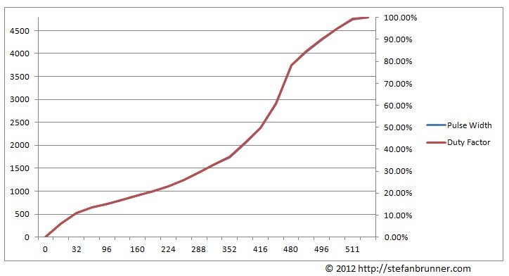
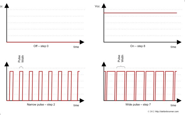 At the charts above you can nicely see how PWM control works. In the upper left corner, power is off and the upper right corner power is on. When the power is on, the pulse width is 1 sec divided by the switching frequency, meaning the length of one pulse is exactely as long until the next pulse starts. With a 210Hz switching frequency the maximal pulse length is 210-1 = 4,762 µs long or one second devided by 210. In the two lower charts you can see left a source with a narrow Pulse Width, delivering little energy to the load, and right one with a wide Pulse Width, delivering more energy to the load.
The picture below shows a screenshot from an oscilloscope, here shown with narrow Pulse Width and hence Low Duty cycle. Do not be confused that the middle coordinate in this chart is also in the middle of the curve. This is not AC voltage but DC. The bottom of the curve is 0V while the top is about 7.5V (but not -7.5V to +7.5V). The curve is just shifted down a bit for more space. The long lines on the bottom are the times when the PWM controller switches power off. The spikes are the pulses - the time the PWM controller switches the power on. Voltage changes from 0V directly to 7.5V. The length of the smaller lines on the top is called the Pulse Width. The Duty Cycle is calculated by dividing the length of the ON time by the length of the OFF time. In the example below this is 816µs / 4,785µs = 0.171 = 17% Duty Cycle.
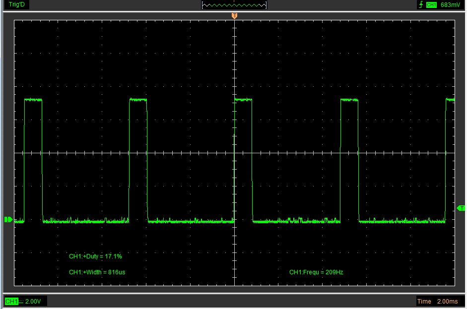
You can see the signal with the step in the ROBO Pro software set to step 2 (in the 8-steps scheme). The Pulse Width is 816µs and the duty cycle is 17.1%, meaning less then a fifth of the energy is provided to the load when compared with the ON, or step 8, setting. If you think about, that a motor is only doing work when the pulse is switched on, it becomes clear why a motor is starting to hum so louder, so further you get down with the steps. If you listen carefully, you will notice a similar hum with speed controlled ceiling fans, tools, or even a subway car; and now you understand why. The ROBO Pro software allows you to either set the steps in an 8-steps or 512-steps scheme. The obvious difference is that with 512 steps, you have much more granular control. But this is not all.
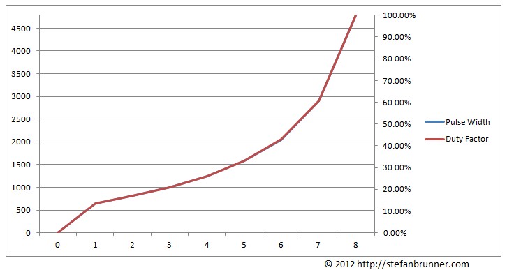 8-steps schemeIn the chart above you can see that the Duty Cycle falls off quiet quickly. While step 8 provides 100% energy to the load, step 7 provides only 61%. The curve is not linear. It falls off quiet quickly and then flatens slowly, providing more granular control on the lower end. This way, a free running motor could be slowed down quiet supstantially. However, a motor under load might need a lot more energy and might just even start spinning at level 6 or so. This is the reason that fischertechnik allows you to set the steps to a 512-steps scheme.
 512-steps scheme
At 512 steps the curve looks different. It is still not linear; however, you gain additionally finer control on the upper levels. For instance step 511 provides a Duty Cycle of 99% whereas only step 448 gets it down to 61%, equivalent to step 7 in the 8-steps scheme. The charts contain two curves, one for the Duty Cycle and one for the Pulse Width. In the TX Controller case, both curves overlap perfectly. The reason for this is that the PWM controller delivers a nice smooth square wave. Not every PWM controller does that and Duty Cycle calculation might be become quiet challanging and involves solving differential equations. (This is by the way what DMM (digital multimeter) vendors call "True RMS". A meter which has True RMS samples the voltage often enough to be able to make such complex calculation internally while simpler models assume a square wave or more often a perfect sinus curve.)
If you wish to connect a TTL or CMOS or any other digital device, only use step 0 and fully on, as in setting the port to step 8 or step 512 in the two schemes. Step levels do not lower the voltage, just pulse it, and you may need a voltage divider if your device needs a lower voltage. Incandescent lamps might be tricked, though, by simply using step 7 for a 6V lamp, like for the older fischertechnik bulbs, for instance.
H-Bridge Configuration
In the beginning I mentioned that there are two ways to configure outputs ports. You might have noticed that ports are labeled in two different ways: O1 to O8 but then also M1 to M4. In fact M1 is equivalent to O1 and O2 together. O stand obviously for Output while M stands for Motor. This is a bit confusing. While the M mode is designed for motors you can of course also plug in a motor into an O port. The difference is that the O port cannot change polarization. The O port itself is always (+) while the other lead needs to be connected to ground which is identical to (-). The means of course that you can change the speed of a motor but not its direction. To allow direction change, you would have to swap (+) and (-). fischertechnik anticipated this and therefore allows you to configure ports in H-bridge configuration. An H-bridge needs two ports and hence M1 requires ports O1, and O2 and M2 requires ports O3 and O4, and so on. If all ports are configured as M ports, than you can only connect four loads. But you do not need to configure all ports as M ports and could also get any combination between eight and four such as one M port which gives you seven outputs, or two M ports which gives you six, or three M ports which gives you five output ports altogether. Remember that I said, that there is a voltage drop when comparing the output voltage to the battery voltage and that this drop is 0.4 or 0.8V depending on configuration? Let's dive into this deeper.
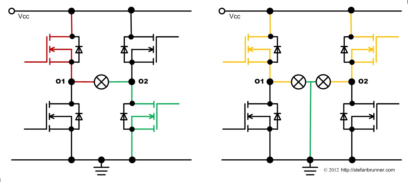 You can see that each port utilizes two MOSFETs. In the first chapter of this series you learned that the PCB hosts two chips which contain eight MOSFETs each. Now the reason for that is clear - there are two per port - why, we will learn soon. The first MOSFET connects with Drain to (+) while the second connect with Source to (-). All Gates are connected via the programmable PWM controller, which also hosts the MOSFETs, to the internal PIO ports of the processor. The O port is connected between the Source of the first MOSFET and the Drain of the second. If the port is off, step is 0 in either scheme, the first MOSFET is switched off and the second MOSFET is switched on, grounding the port. There are two ways to connect a load to such a port. Normally, you would connect it between the O port and one of the green ground connectors which is demonstrated in the picture above on the right. This way you can use all eight ports. However, for convinience of wiring, you can also connect the load between two O ports such as between O1 and O2. However, you can only activate, hence setting the step to anything larger than 0, on one of them. The second one needs to stay in OFF position with the step set to 0 to provide a ground. Each MOSFET has a voltage drop of 0.4V. Therefore, in the first case, you get 8.4V with a full battery minus 0.4V = 8V and in the second case 8.4V - 2 * 0.4V = 7.6V. Your actually milleage may vary depending on charge level of the battery, whether you use a 9V stabilized power supply, or the length of wire your load connects to and how much current it draws. The actual power delivered to a motor depends on supply voltage and is maximal ( 9V - 0.4V ) * 1A = 8.6 Watts. Just do not forget that all ports together cannot draw more than 2A and you need a power source such the fischertechnik Accu Set, which can provide 2.5A to the TX Controller. The fischertechnik battery may be able to do this just for a short time before its internal thermal kicks in or the battery is discharged.

Let's talk about why we need two MOSFETs for each port. The answer is so that an H-bridge can be configured in order to change polarity. If you look carefully at the figure above, you see that the four MOSFETs resemble the character "H" with the motor in the middle. On the left, the upper MOSFET of port O1 is switched on while the lower MOSFET is switched off, connecting O1 to (+). On O2 we see just the reverse. The upper MOSFET is switched off and the lower is switched on, the default setting of each port, connecting O2 to ground or (-). When we want to change the spin direction, have a look at the right figure, we simply reverse that, connecting O1 to (-) and O2 to (+). On an M port the maximum power is ( 9V - 2 * 0.4V ) * 1A = 8.2 Watts. Keep in mind that the actual wattage a motor consumes depends on the motor and its load. A free spinning motor will consume much less power than a motor doing hard work. As mentioned above, a motor doing hard work, might not start before you raise the Duty Cycle above 50% like to something such as step 6 and step 400 or above in the two schemes. You might have to try this out for the different models you build. If the port is not switched on fully, the actual wattage is the wattage at full, step 8 or step 512, multiplied by the Duty Cycle. You see, with PWM control, nothing goes to waste. Only the power delivered is consumed and no power is burned (and released as heat) as this is the case with variable controls of the past such as the old fischertechnik power supplies from like 10 years or more back. In the EU, those are actually outlawed for the sake of power conservance.
Connecting Encoder Motors
In order to spin a motor not at a certain speed measured in rounds per minute (RPM) but to something like a number of spins or even a fraction of a spin, we need something special. Computer hard drives and printers use stepper motors. Stepper motors are motors with individual electro magnetic windings which are controlled by a special driver so that the motor spins a fraction of a turn, such as a single degree. Former sets from fischertechnik had those stepper motors. Stepper motors which provide enough power to make a model move are quiet expensive wich does not make them good candidates for educational kits where a certain price point needs to be met. Not just that, but they also would require two H-bridges, consuming four O ports.
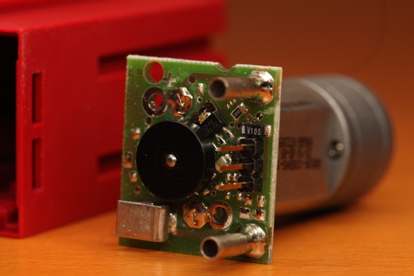
A convinient solution is an encoder motor. An encoder motor has two elements: a motor with gear box and an encoder sensor. You can see both in the picture above. The gear box is the silver round drum at the end of the motor. (A bit fuzzy, still learning on my wife's DSLR.) The encoder is made from a Hall sensor, which is a sensor detecting magnetic fields, and a magnet. The black disc on the PCB is a magnet connected to the motor's axle which spins with that axle. The larger black chip partly under the magnet on the top/right corner is the Hall sensor. This particular Hall sensor turns low everytime the south pole of the magnet passes by. Low means, it pulls the digital input to ground. The gear box is important as a normal motor cannot be made to spin a fraction of a turn, so that we need to gear down the motor. The gears turns the axle on the outside where you connect things one time for each 75 spins of the motor itself, hence the Hall sensor delivers 75 pulses for each complete turn. Or in other words, you can control this motor in fractions of 360 degress divided by 75, about in steps four degrees.
Because of the encoder, the encoder motor additionally has to be connected to an input port. Because digital mode Universal ports are really multiplexed analog ports in digital emulation, there are not fast enough for a fast spinning motor to sense the signals from the decoder. Hence, the encoder motor is connected to the Counter ports which are directly connected to PIO pins on the processor. The Hall sensor in the encoder motors needs (+) and (-) and has also needs an input connection. Hence, the encoder motor needs one M port which are two O ports, and one Counter port, in addition to a connection to the red 9V connector. (Technically, you do not need an M port and one single O port is sufficient if only one direction is desired.)
I2C
I2C is not just an Input but also an Output - or in other words - is a bidirectional bus. A Master, the processor here, can poll many different slave devices and poll or send messages to them. Both input as well as output devices can typically send and receive messages because they contain their own little microcontrollers. The address space is huge, the SAM9260, which is the core of the fischertechnik ROBO TX Controller, has an address space of 10 bits which could control 1024 input or ouput devices. Typical output devices are displays, including color screens such as those used in cell phones, and motor controllers, such as those to control steppers as utilized in robots or CNC machines.
I2C is supported with firmware 1.30 which was announced together with the new ROBO TX ElectroPneumatic set summer 2012. You need RoboPro 3.1.3 or higher. A free update is provided on fischertechnik's Web site under Downloads, both for RoboPro as well as GNU C and Microsoft Visual Studio.
< Previous